Import Network Description from Tables
The Import Network Description From Tables wizard can import network descriptions on a primitive table based format.
As most computer software is able to export data to a primitive table based format, this wizard may be the only option for importing network information from, or integrating HUGIN with a thirdparty program unaware of the HUGIN Net language.
A primitive table consists of rows and columns. Individual columns are separated by symbols <SPACE>, <TAB> or comma (‘,’). Rows are separated by either <NEW-LINE> or <CARRIAGE-RETURN><NEW-LINE>.
Importing a network description is performed in three steps:
Parse variable definitions
Parse link definitions
Parse table descriptions
Each kind of description is a file containing a primitive table with only a few formatting conventions.
Variable definitions
The variable definitions table consists of three columns:
<NAME> <TYPE> <STATE>
The first column <NAME> indicates node name. A node name must begin with a letter and only contain characters [a-z][A-Z][0-9].
The second column <TYPE> indicates node type. Valid values are:
The third column <STATE> specify information about node states and is required for labelled, numbered and interval nodes. The specific number of states for a node is determined by the number of lines pertaining to specifying the particular node. States are created in the order they appear in the file. Values have different meaning depending on node type:
Labelled nodes: Value specify state label. The label must be enclosed in quotation marks (”) if it contains any whitespace characters or characters outside the range [a-z][A-Z][0-9]. To specify n states, the node must appear in n lines in the file.
Numbered nodes: Value specify numeric state value. Value must be a number which can be specified using characters [0-9] and dot (‘.’). To specify n states, the node must appear in n lines in the file.
Interval nodes: Value specify state interval endpoints. Value must be a number which can be specified using characters [0-9] and dot (‘.’). Positive and negative infinity is specified by the string ‘infinity’ and ‘-infinity’. To specify n states, the node must appear in n + 1 lines in the file. First line indicate lower bound for first interval, following lines indicate upper bound for previous interval and lower bound for current interval. The last line n + 1 indicate upper bound for state n.
Link definitions
The link definitions table consists of a line for each node specifying the parents, consisting of a variable number of columns:
<NODE> ( <PARENT-NODE>)*
The value in the first column <NODE> indicates a node and values in each of the following <PARENT-NODE> columns specify the parents of this node. Thus the network structure can effectively be described as a number of lines in the link definitions table.
Table descriptions
Node table descriptions are specified in a number of separate files, one per node. Each file contains a primitive table describing the CPT for a particular node. Table descriptions distinguish between tables with model nodes and tables without model nodes.
Tables without model nodes:
first line |
<NODE> |
|
second line |
<PARENT-LIST> |
<NODE-STATE-LIST> |
following lines |
<PARENT-CONFIGURATION> |
<PROBABILITY-LIST> |
The <PARENT-LIST> is a list of parent node names:
<PARENT-LIST> := (<PARENT-NODE> )*
The <NODE-STATE-LIST> is a list of states for the node specified in <NODE>. A state can be either a state number or a state label:
<NODE-STATE-LIST> := (#<STATE-NUMBER> |<STATE-LABEL> )+
When specifying tables for continuous nodes the <NODE-STATE-LIST> instead denotes alpha and variance:
<NODE-STATE-LIST> := alpha variance
The <PARENT-CONFIGURATION> specify a unique configuration of the parent nodes. The list identifies, in parent node order, a state for each parent node specified in <PARENT-LIST>. A state can be either a state number or a state label:
<PARENT-CONFIGURATION> := (#<PARENT-STATE-NUMBER> |<PARENT-STATE-LABEL> )*
The <PROBABILITY-LIST> specifies the probabillity for the particular configuration in <PARENT-CONFIGURATION> for each state in <NODE-STATE-LIST>:
<PROBABILITY-LIST> := (<NUMBER> )+
In the case of continuous nodes, the <PROBABILITY-LIST> specifies the values for mean and variance:
<PROBABILITY-LIST> := <NUMBER-MEAN> <NUMBER-VARIANCE>
Tables for function nodes without model nodes
Specifying a table for a function node is even simpler, as only an expression must be supplied in the form of a quoted string. The table thus consists of a single line with two columns:
single line |
<NODE> |
<EXPRESSION-AS-STRING |
Tables with model variables Specifying a table for a node with model variables is almost the same as without model variables. The difference is the second line, which only contains a <PARENT-LIST> and the following lines which instead of a <PROBABILITY-LIST> contains the expression for the node based on the given parent configuration:
first line |
<NODE> |
|
second line |
<PARENT-LIST> |
|
following lines |
<PARENT-CONFIGURATION> |
<EXPRESSION-AS-STRING> |
Example
This example is based on the Chest Clinic example and demonstrates what the Chest Clinic network would look like on primitive tables form.
Variable definitions
Link definitions
Table descriptions
Importing in HUGIN
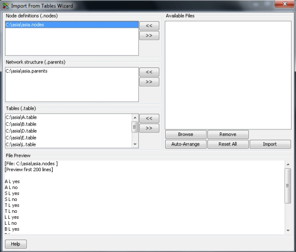
To import the network description click File -> Import -> Import network from tables. The Import From Tables Wizard appears, see Figure 1.

Figure 1: Import From Tables Wizard
Importing:
Browse for primitive table files by clicking the Browse button.
Arrange files onto appropriate lists using the << and >> buttons to move files between the Available Files list and Node definitions, Network Structure and Tables lists. Clicking the Auto-Arrange button arranges the lists based on file endings (.nodes, .parents, .table).
Click on a file to preview its contents.
Finally click Import.
