Expression Builder Wizard
The Expression Builder Wizard (Figure 1) gathers many functions related to adding expressions on a Node Table. It consists of the Options panel, The Expression Builder Panel and the Table Panel. The main purpose of this wizard is to make it easier to build an expression by assisting the user in selecting the correct type of expression the current node supports, selecting the correct type of parent nodes to be used in an expression and dividing the whole process into steps that allows him to concentrate on building one simple expression at a time without losing the overview of the complete expression.
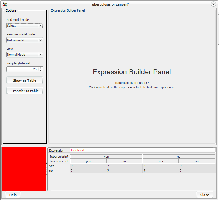
Figure 1. Expression Builder Wizard
To build an expression, select one of the felts in the expression table where it shows “Undefined” (Figure 1). The Expression Builder Panel (Figure 1a) that is relevant for the type of the current node is now visible. Select the desired function category and then a function from the Function Name combo box to view the appropriate argument fields. Type expressions in the argument fields or press the “f(x)” button next to them to build an expression for the corresponding field. To insert a parent, right click and select from the list that appears.
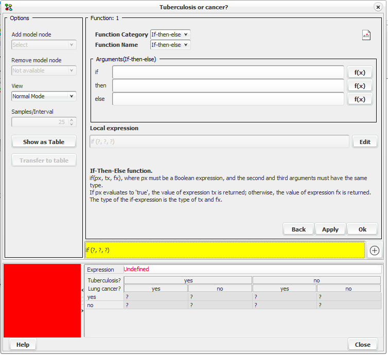
Figure 1a. The Expression Builder Panel is displayed for the node “Tuberculosis or Cancer”.
After building the expression press the “Apply” button and then the “Show as Table” button to confirm that the expression is built correctly. For more information about building an expression, see Expression Builder Panel.
Options Panel
The Option Panel (Figure 2) offers functionalities that are also available in the Node Table Frame menu.
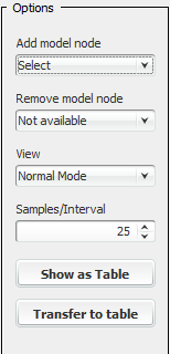
Figure 2. The Options Panel.
The Add/Remove model node combo boxes as implied, allows the user to add or remove parent nodes to the expression table .

Figure 2a. Selecting “Has tuberculosis”.

Figure 2b. The table after adding a model node.
Figures 2a and 2b show how the Node table looks like after adding the parent node “Has tuberculosis” on the expression table model. This allows the specification of two different expressions, one for each state of the added parent node. To remove the node from the model, select it in the “Remove model node” combo box. The view combo box supports three different views of the values in the node table.
Normal Mode: Only digits are displayed in every cpt index.
Bar Mode: Both digits and a bar representing the value are displayed.
Pure Bar Mode: Only a bar representing the value is displayed.
Expression Builder Panel
The Expression Builder Panel is where the actual building of the expressions takes place after selecting a cell in the expression table. It guides the user through the construction of Expressions, which are the cornerstones of the Table Generator, using a series of steps. The current step is displayed on the top left corner. In the example shown in Figure 3 the current step is 1 (Function 1).
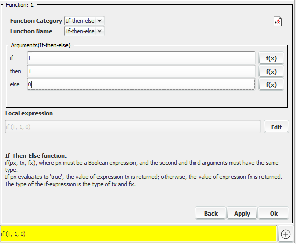
Figure 3: The Expression Builder Panel showing an if - then - else expression
The Expression Builder Panel assists the user in building expressions by providing a simple user interface for selecting a function or an operator and specifying its arguments.
The combo boxes at the top of the panel (“Function category” and “Function Name”), show the functions available (the actual set of functions depends on the type of the node associated with the current node table). Selecting a “Function Category” populates the “Function Name” combo box with the corresponding functions allowing the user to select. Figure 3a shows the function categories associated with a “Numbered” node. The functions are organized in a number of categories to make it faster to find a particular function.
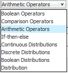
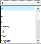
Figure 3a. Selecting Arithmetic Operators in the “Function Category” combo box will allow the selection of arithmetic operators in the “Function Name” combo box.
The arguments panel (Figure 3b) is where the arguments of the expression can be specified. Each argument is itself an expression and can therefore be built in the same way as the current expression. Pressing the “f(x)” button next to the argument text field, will start “step 2” allowing the user to build an expression for that argument.

Figure 3b. The arguments panel. Selecting the parent node “Has tuberculosis” of type “Labelled”, to insert in the if argument field.
The use of a parent node in an expression is possible by using its unique name. Figure 3b shows how to insert a parent node in an expression. By right clicking on an argument field a popup appears showing a list of the parent nodes. Pointing on a node displays its type, to help the user decide if it can be used in the current expression, because not all types can be used on all expressions. A short description of the currently editing expression is displayed under the local expression field (Figure 3) and among other things it describes what type of nodes can be used. When selecting a parent node from the list it is inserted into the argument field. Only discrete chance nodes and decision nodes can appear in expressions.
When editing in the argument fields, the changes made are also shown in the “Local expression” field and the colored field at the bottom. These fields display the expressions in their proper form replacing arguments that are not yet specified with the “?” mark.
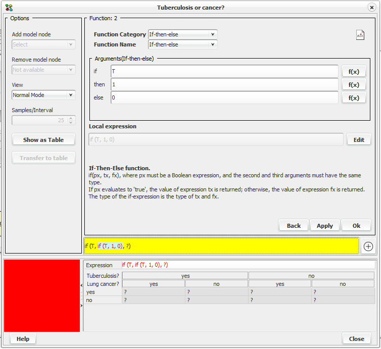
Figure 3c. The local expression represents the current editing expression in the arguments panel and the colored field at the bottom shows the global expression.
The “Current expression” represents the sub expression that is being edited in the current step and the colored field displays the whole expression with the currently editing expression highlighted to help the user keep a perspective of the process. The “plus” button next to the colored field, initializes the “expression viewer” that allows the user to view a very long expression that might not be possible to display in the standard text field.
Figure 3c shows that we are currently in step two (Function 2. Upper left corner) and we are building an if - then - else expression with arguments T, 1 and 0. The “Current expression” shows the written form of the expression ( if (T, 1, 0) ). The colored field shows that the current expression is used as the second argument in an if - then - else expression, with the node “T” as the first argument and the last argument not specified yet.
The expression builder can be switched to edit mode by pressing the “Edit” button allowing the user to manually type in the “Current expression” field, just like it can be done in the node table frame. The insertion of a parent node is done in the same way as described above.
It is possible to return to build mode again by pressing again the same button (now displaying “Build”). If the expression typed in edit mode (local expression field) can be parsed correctly, the appropriate arguments panel will be displayed and the argument fields will be populated.
When pressing the “Back” button the Expression Builder returns to the previous step if there is one or to its initial state, ignoring eventual changes.
The “Apply” button inserts the expression in the expression table without parcing for errors. The “Ok” button closes the current arguments panel, and returns the expression created to the target arguments field of the previous step or to the expression table if currently in step 1. After inserting the expression in the expression table press the “Show As Table” button (Options Panel) to parse for errors.
