Introduction to Object-Oriented Networks
An Object-Oriented Network is a network (i.e., Bayesian network or LIMID model) that, in addition to the usual nodes, contains instance nodes. An instance node is a node representing an instance of another network. In other words, an instance node represents a subnet. Therefore, following standard object-oriented terminology, an object-oriented network is often referred to as a class. Of course, the network of which instances exist in other networks can itself contain instance nodes, whereby an object-oriented network can be viewed as a hierarchical description (or model) of a problem domain. There are three main advantages of constructing a network using instance nodes, as described in the following.
The model construction activity most often involves repeated changes of level of abstraction. That is, it is performed in a top-down fashion, a bottom-up fashion, or a mix of the two. Such repeated changes of focus are due partly to the fact that humans naturally think about systems in terms of hierarchies of abstractions and partly due to lack of ability to mentally capture all details of a complex system simultaneously. The use of instance nodes provides support for working with different levels of abstraction in constructing network models.
As systems often are composed of collections of identical or almost identical components, models of systems often contain repetitive patterns (i.e., commonly occurring solutions or problem types). In Bayesian networks and LIMIDs, such patterns are network fragments. The notion of instance nodes makes it very easy to construct multiple identical instances of a network fragment.
Describing a network in a hierarchical fashion often makes the network much less cluttered, and thus provides a much better means of communicating ideas among knowledge engineers and users.
The HUGIN Graphical User Interface 6.* supports construction of object-oriented networks in the basic interpretation of the concept mentioned above. A fully object-oriented paradigm for constructing Bayesian networks and LIMIDs should also support the notions of subclasses and inheritance, as known from object-oriented programming languages. Thus, the basic mechanisms provided by the HUGIN Graphical User Interface 6.* supports the construction of what might be called hierarchical networks.
Interface nodes
An instance node connects to other nodes via some of the (basic) nodes in the copy of the network (the master) of which it is an instance. (Note that an instance node should be thought of as a copy of the network of which it is an instance.) These nodes are known as interface nodes. As we wish to support information hiding, the interface nodes only comprise a subset of the nodes in the master network. Interface nodes are subdivided into a set of input nodes and output nodes.
Input nodes of an instance of a master network are not real nodes but only to be considered as placeholders for (basic) nodes of the network(s) containing instances of the master network. These basic nodes are said to be bound to the input nodes (and vice versa). Note that if an input node of an instance hasn’t been bound, a default potential (probability table) will be associated with it. The probabilities in this table is specified in the master network. Output nodes of an instance of a master network are real nodes that can be specified as parents of nodes in the network containing the instance node or can be bound to an input node of another instance node of the network. The following example demonstrates what all this means.
The Disease Example Revisited
In the Bayesian Networks section, we presented the dynamic Bayesian network example shown in Figure 1. This example illustrates the progression of diseases D1 and D2 over time such that D1 at the next time slice depends on D1 at the current time slice, and similarly for D2. S1 and S2 represent symptoms for the diseases. In Figure 1 we have only indicated the model for two consecutive time slices.
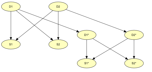
Figure 1: An example of Dynamic Bayesian Network (DBN).
Creating the model in this fashion covering several time slices is a tedious job. Assuming that the structures and the tables of the time slices are identical, and that the transition probabilities P(D1|D1 prev) and P(D2|D2 prev) identical for all time slices (which is often the case in real-world applications), constructing such a time-sliced model can be done very elegantly using instance nodes. First, we create the model for a single time slice (see Figure 2). This model takes as input the disease nodes of the previous time slice, and the disease nodes D1 and D2 act as output nodes, since they should be bound to the input nodes of the next time slice. The input nodes are indicated in Figure 2 with dashed outlines.
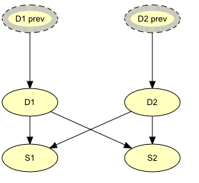
Figure 2: BN representing a single time slice in the disease problem.
The transition probabilities P(D1|D1 prev) and P(D2|D2 prev) describing the temporal behavior as well as the probabilities describing the atemporal behavior are contained in this model.
Second, we construct a model covering, say 10, time slices simply by creating k instances of the network in Figure 1 and bind the outputs of time slice 1 to the inputs of time slice 2, etc. In Figure 3, we have shown the resulting model for k=3.
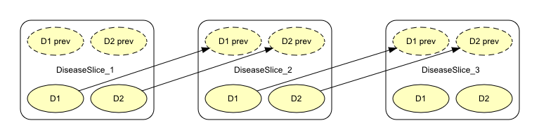
Figure 3: A 3-time slices dynamic Bayesian network (DBN) specified as an object-oriented network.
If there are many instance nodes, the object-oriented network might appear somewhat cluttered. Therefore, once the binding links have been created, we most often prefer to collapse the instance nodes, as shown in Figure 4.
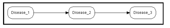
Figure 4: The DBN in Figure 3 with collapsed instance nodes.
Accident Example
The following example was first used in Koller & Pfeffer (1997) Object-Oriented Bayesian Networks, Proceedings of the 13th Conf. on UAI. The network (see Figure 5) models a car accident situation, and contains instance nodes for subnetworks representing characteristics of the driver, the car, and the road.
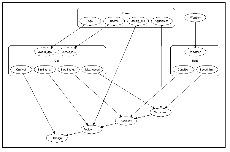
Figure 5: An object-oriented network describing a car accident situation.
Again, collapsing the instance nodes makes the network less cluttered, as illustrated in Figure 6.
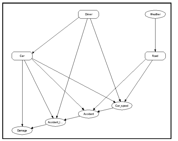
Figure 6: The network in Figure 5 with instance nodes collapsed.
Now, the network of which the car node is an instance contains itself several instance nodes, as shown in Figure 7.
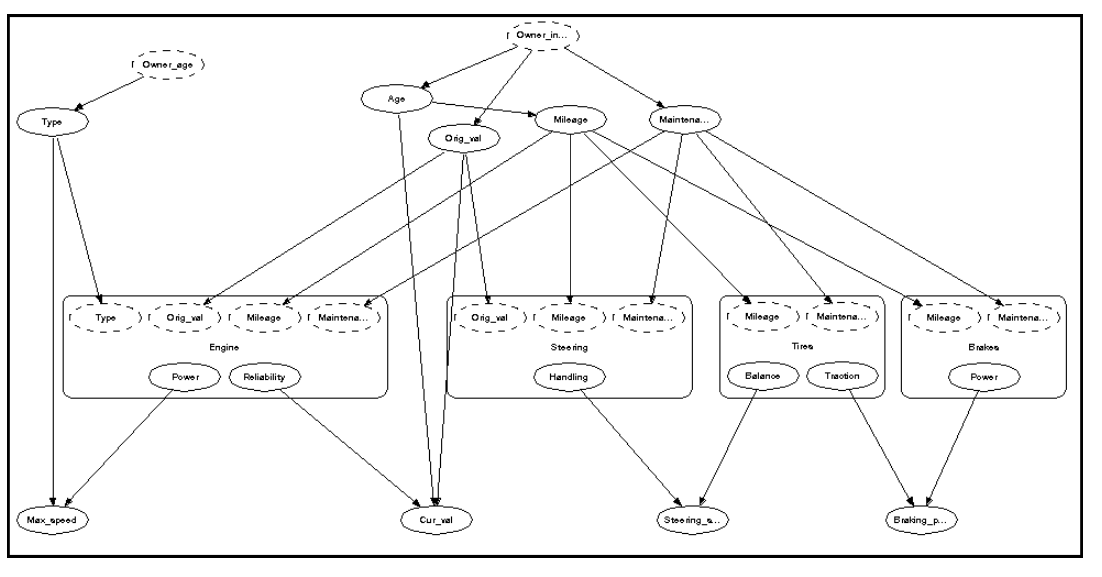
Figure 7: The network of which the car node is an instance.
Figure 7: The network of which the car node is an instance. The benefit of constructing this model using the object-oriented network technology is indeed clear. HUGIN provides you with a tool to construct object-oriented networks. After constructing an object-oriented network, you can do belief revision, belief updating, and much more, just as for ordinary BNs. To learn how to build object-oriented networks using the HUGIN Graphical User Interface, please consult the How to Build OOBNs tutorial.